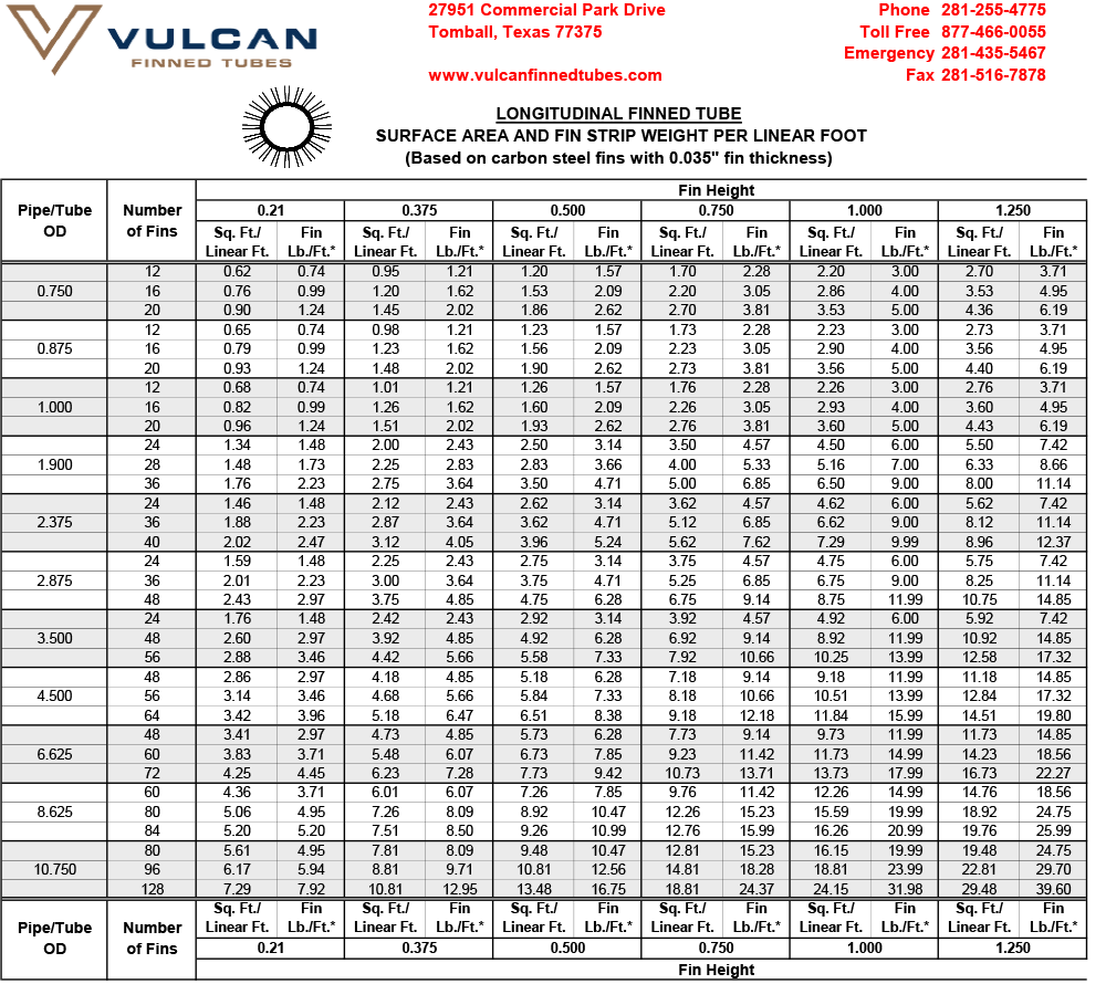
Vulcan’s Welded Longitudinal Finned Tubes are produced by resistance welding fins in the longitudinal direction along the length of the tube. The fin strip is first formed into a U-shaped channel, such that each leg of the U will form a fin. The channels are cut to the appropriate length and then oriented along the length of the tube and resistance welded in place. The channels are welded in pairs, diametrically opposed — therefore the number of fins specified must always be a multiple of four.
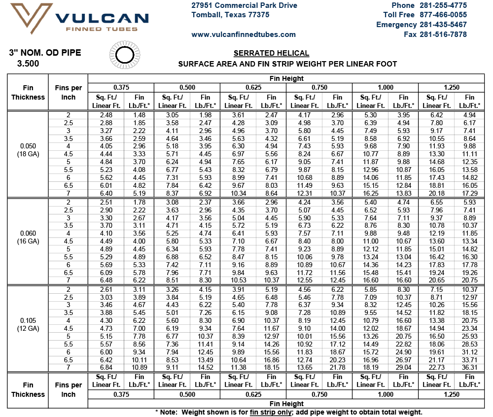
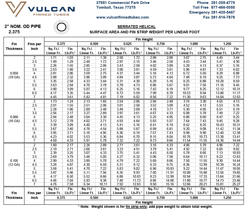
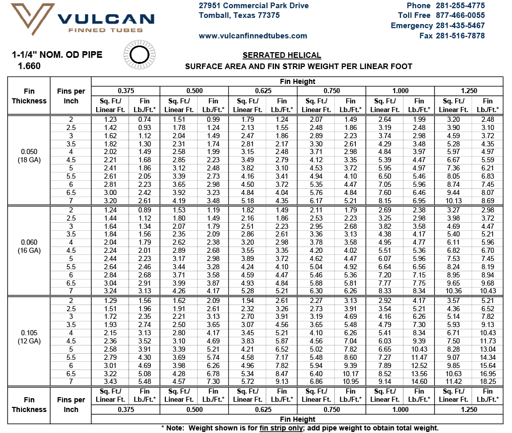
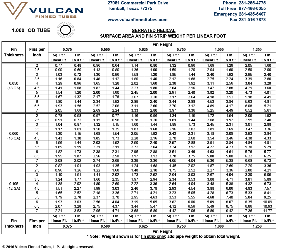
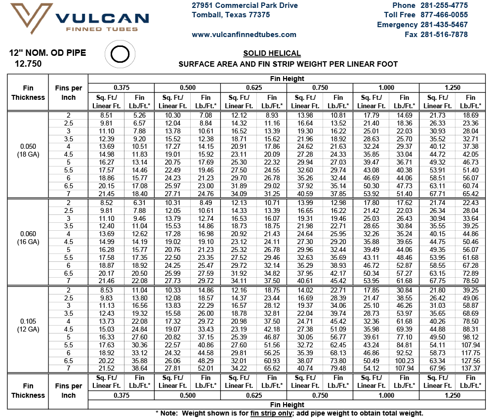
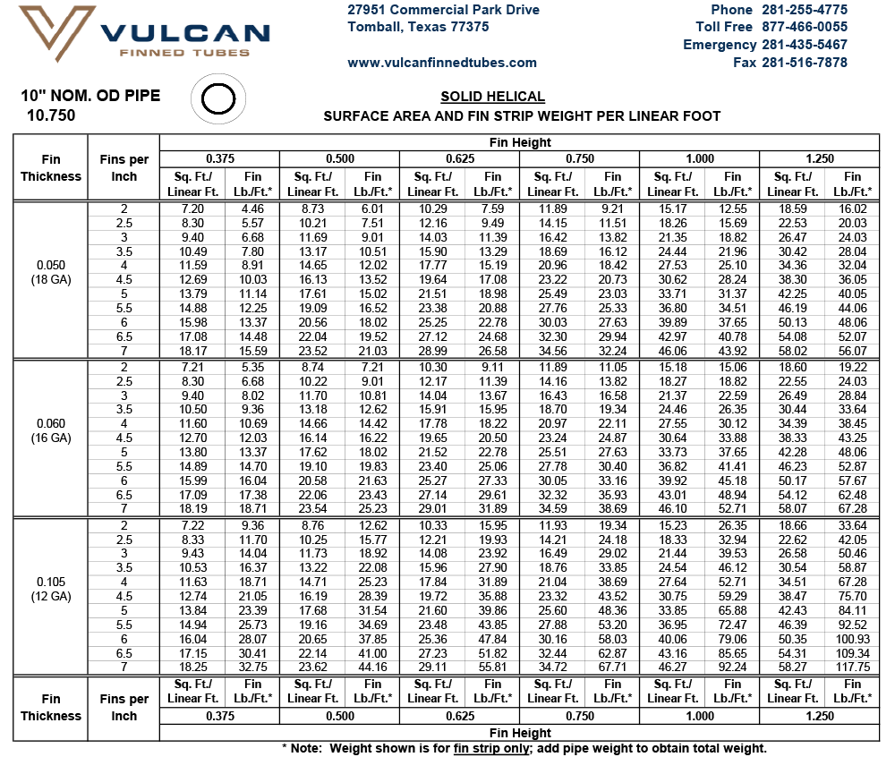
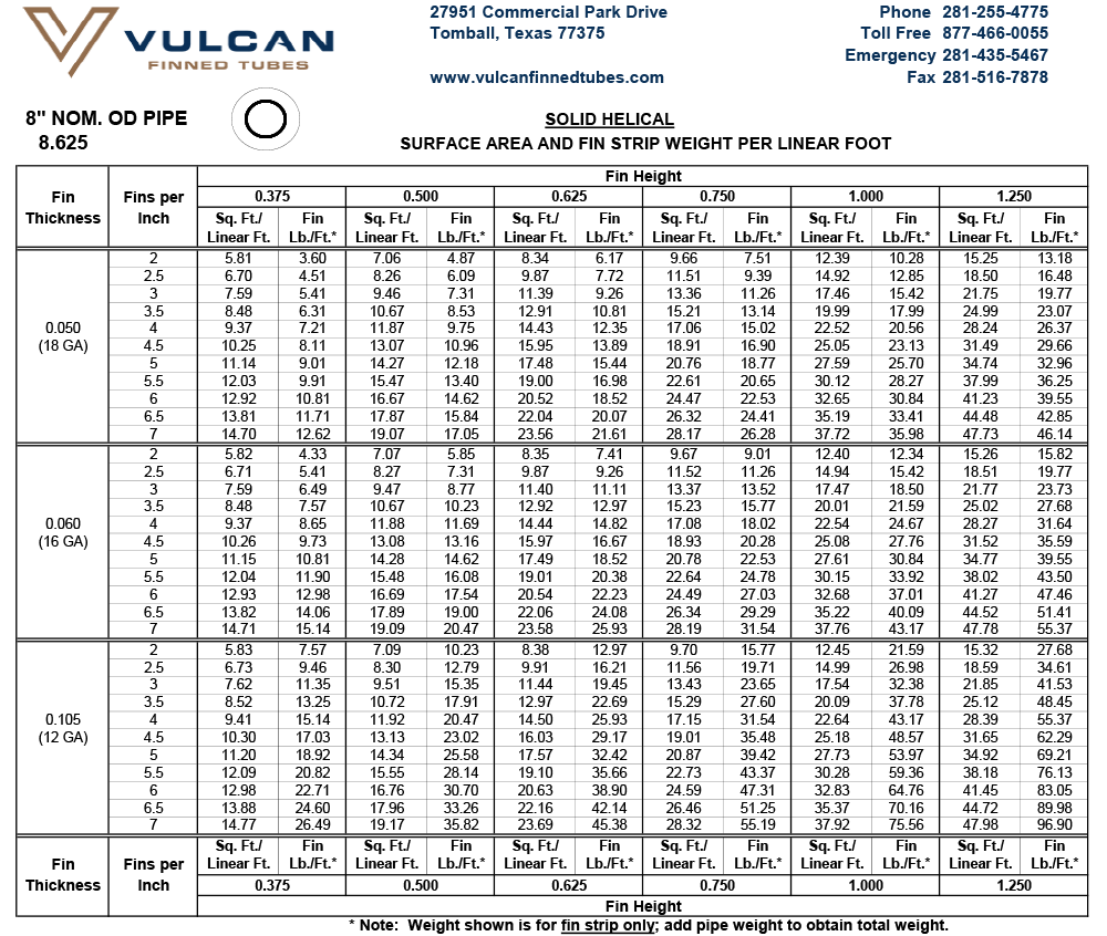
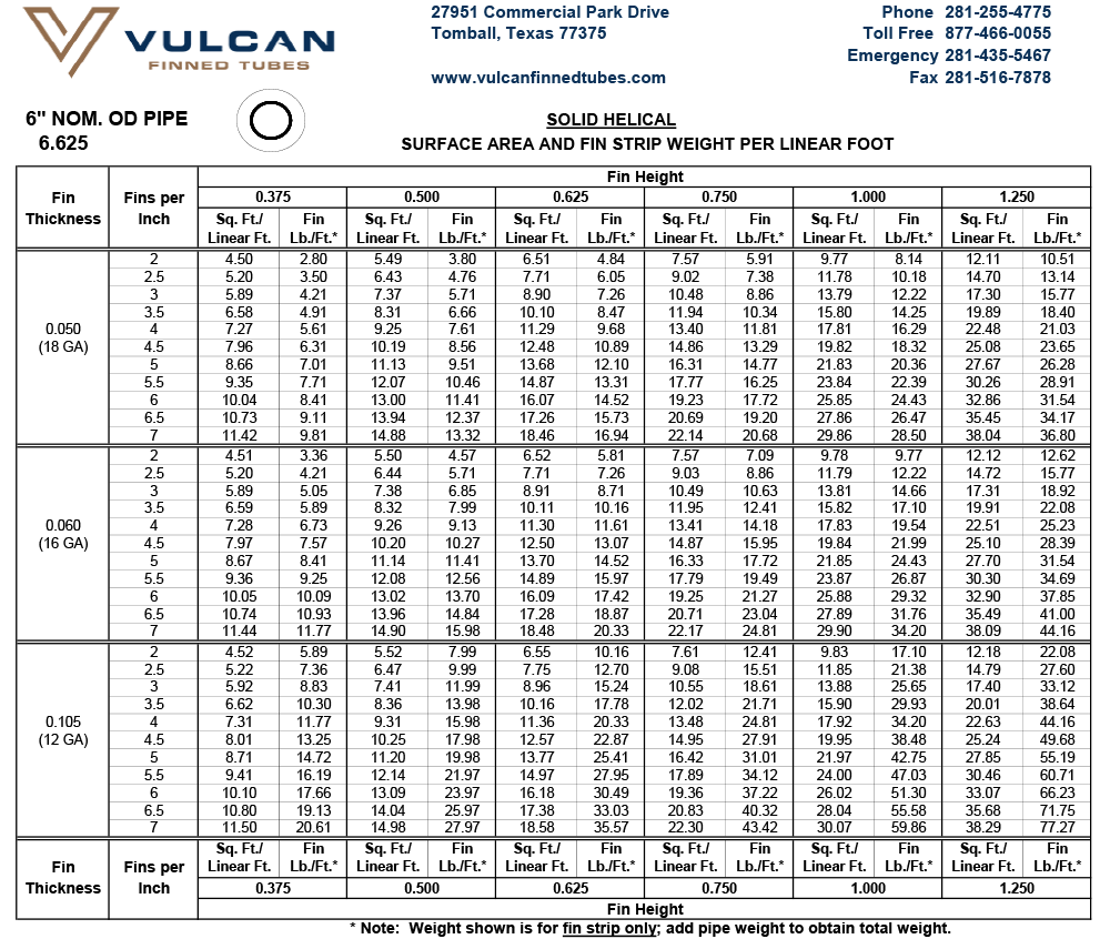
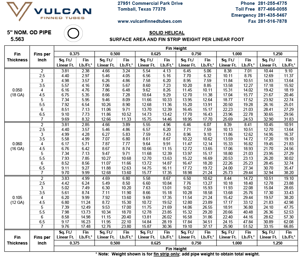
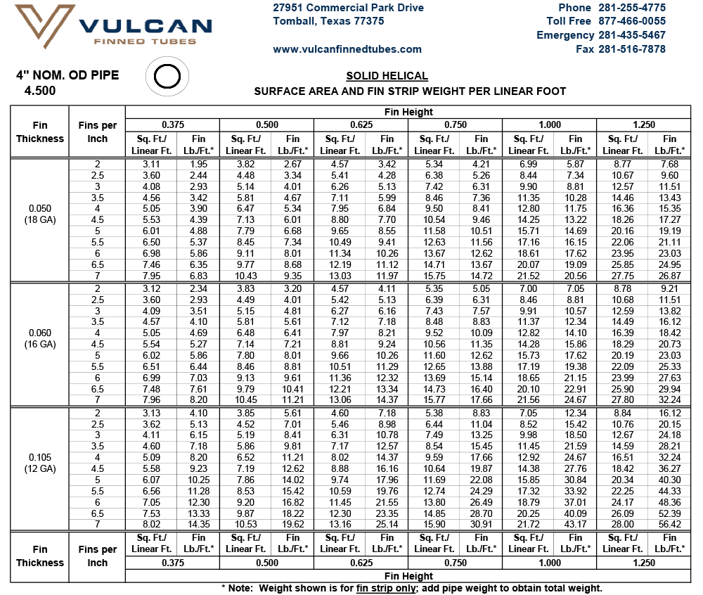
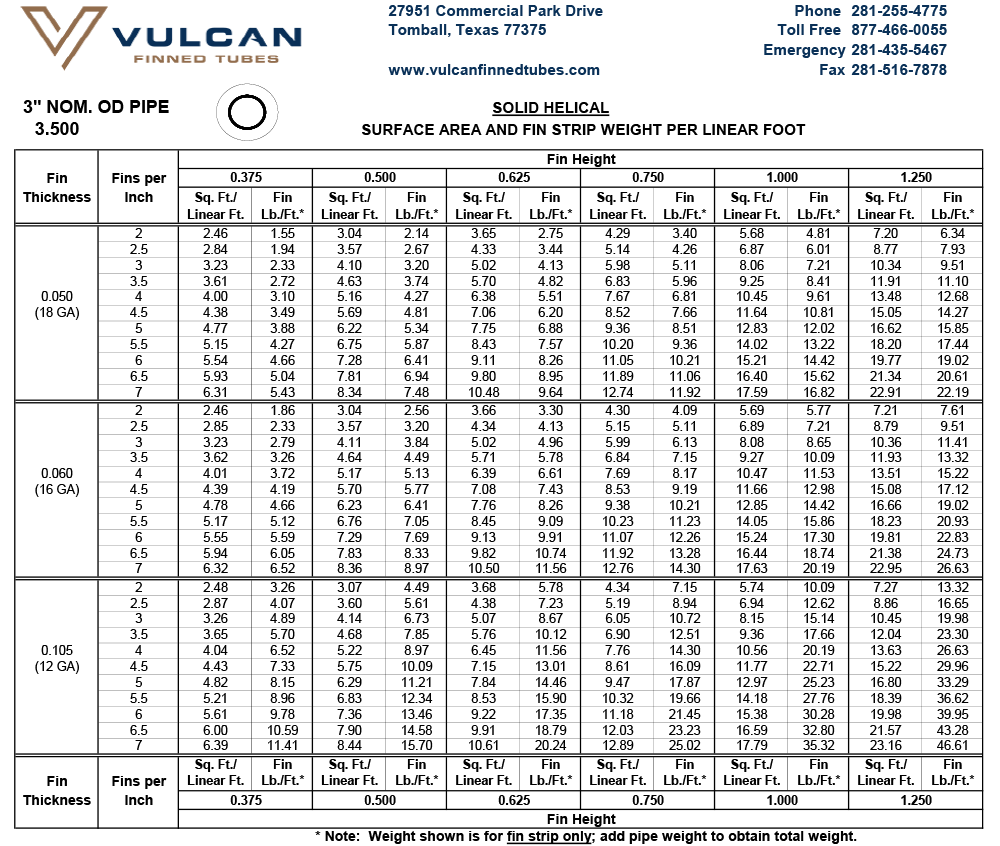
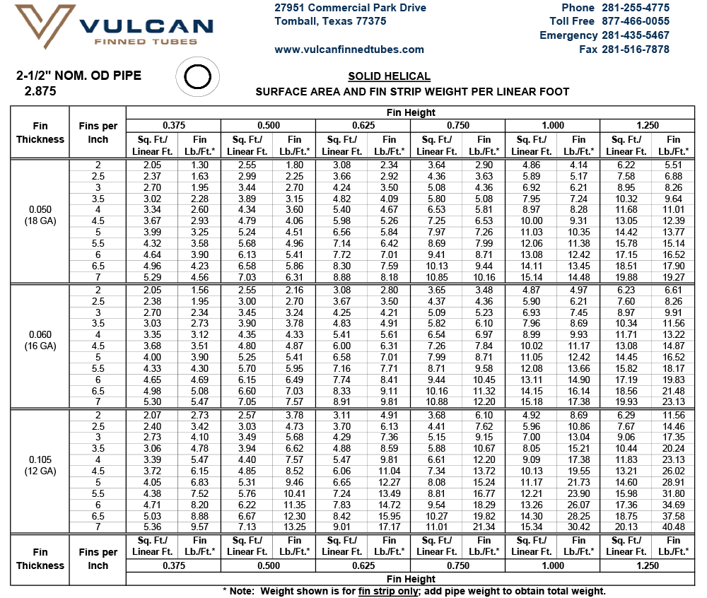
For a given pipe or tube size, the desired heat transfer surface area per unit length of tube can be obtained by specifying the appropriate fin height and number of fins. The maximum number of fins is dependent upon the tube outside diameter — larger OD tube can accommodate a greater number of fins. See Design Information for extensive tables of surface areas and fin weights.
Some customers specify that the longitudinal finned tubes be “Cut and Twisted.” This operation consists of cutting through the fin channels circumferentially at specified intervals along the tube length. The fins are then bent (or “twisted”) on one side of each cut, creating a discontinuity that promotes turbulent fluid flow, thereby enhancing heat transfer efficiency.
The following table shows Vulcan’s manufacturing capabilities for longitudinal finned tube:
| Weld Process | Resistance Weld |
| Tube/Pipe Size | 0.75″ to 10.75″ outside diameter |
| Fin Height | 0.21″ to 1.50″ |
| Fin Thickness | 20ga (.035″) to 18ga (.050″) |
| Number of Fins | Dependent on tube OD |
| Materials | Any material combination that can be resistance welded |
| Tube Length | No practical limit |
* This table should be used as a general guide to our capabilities for Welded Longitudinal Finned Tubes. Grade of material, tube outside diameter to fin height and other factors may limit these capabilities. Please call us for guidance when designing your next finned tube.
Like welded helical finned tubes, this welded configuration can be used for practically any heat transfer application, and is particularly suited to high temperature, high pressure applications with high fin-side temperatures. The choice of longitudinal finned tubes versus helical finned tubes seems to be governed mainly by geometric considerations. For example, some heater configurations consist of finned tubes inserted inside other tubes — longitudinal finned tubes are the obvious choice for such applications. In other cases, users prefer longitudinal finned tubes for installations where the tube will be oriented in a vertical direction — the fin orientation facilitates fluid drainage on the fin side of the tube. The longitudinal fin configuration is most commonly used in shell and tube type applications such as in double-pipe and multi-pipe heat exchangers where the longitudinal finned tube is telescoped inside the bore of a larger tube shell. Heat is transferred between the fluid passing through the bore of the finned tube and the fluid passing through the bore of the shell. Fluids passing through the bore of the shell are forced between the longitudinal fins. In this case, a helical fin would block the flow of the fluid, rather than allowing the fluid to run between the fins.
To learn more about this product see Vulcan’s Standard Specifications for Welded Longitudinal Finned Tubes.